A Guide to GIT using spatial analogies

Some developers find Git takes a little getting used to, claiming that it is conceptually convoluted compared to other distributed version control systems. I used to number myself amongst them.

Happily, I've found that a couple of simple spatial analogies have made me proficient and fluent in using Git's command-line interface.

One of the things that tripped me up as a novice user was the way Git handles branches. Unlike more primitive version control systems, git repositories are not linear, they support branching, and are thus best visualised as trees, upon the nodes of which your current commit may add new leaf nodes. To visualise this, it's simplest to think of the state of your repository as a point in a high-dimensional 'code-space', in which branches are represented as n-dimensional membranes, mapping the spatial loci of successive commits onto the projected manifold of each cloned repository.

Branches as n-branes

Update: There is, of course, a fabulously insightful commentary on reddit.

Update: Thanks folks. You've made my usual one or two hundred daily visitors look kinda paltry:

spike in daily traffic graph

Rerun unit tests whenever files update

In which I once again indulge my obscure command-line fetish.

I often spend hours of my day cycling through:

  • Edit code and its unit tests
  • Save my changes
  • Push a button or change window focus to explicitly re-run the code's unit tests.

Oh frabjous day, the grinding manual labour of the last of these three steps can now be banished forever, courtesy of rerun, a command line Python script that re-runs a given command whenever it detects changes to any of the files in the current directory, or its subdirectories.

https://github.com/tartley/rerun

Update: It's Python 2 & 3, and works great on Windows XP, Macs and Ubuntu.

For example: I had previously bound f6 in Vim to 'run the current file's unit tests. Now I've bound shift-f6 to rerun the current file's unit tests in a new console window. This pops up a new window showing the test results. I then continue editing in Vim, and whenever I hit save, the unit tests are re-run in the other window. All the while the focus stays on my editor. It's really sweet!

Thanks for the original idea goes to to the bash command watch, and an old (now offline) blog post by Jeff Winkler.

Flying High: OpenGL from Python, Part 2

This is second in a series of articles about algorithmically generating geometry to drive OpenGL from Python.

<< Back to part 1

Last time we got as far as creating some instances of our super-simple Shape class, and having Glyph and Render classes convert those to arrays for OpenGL and render them. This time, we start using that infrastructure to create some more interesting geometries, which means there's less code, and more pretty pictures.


Composite Shapes

In order to create more complex shapes by composing instances of existing ones, we need a simple composite shape:

class MultiShape(object):

    def __init__(self):
        self.children = []
        self.matrices = []

    def add(self, child, pos=None, orientation=None):
        self.children.append(child)
        self.matrices.append(Matrix(pos, orientation))

A MultiShape contains a list of child Shapes, and a matrix for each child, indicating the child's position and orientation relative to the MultiShape's front-and-center.

This is probably as good a point as any to confess that for the purposes of this demo, I ended up writing my own Matrix class, along with my own Orientation class. Even my Vec3, which earlier I showed you defined as a named tuple, gradually started to sprout some methods, until it became a fully-formed custom vector class. This was pretty silly - it easily doubled the size of my code-base, and while it felt like rewarding and productive work, it was actually a waste of time. With hindsight, I should have predicted this would happen, and started out using an existing library for things like this, such as Euclid or Numpy. Way it goes.

Anyhow, if a Multishape is going to be usable wherever a Shape is currently used, it needs to provide the same interface, which luckily is very simple - it just needs to provide iterables of vertices, faces and face_colors. Here is how MultiShape provides a sequence of vertices, by chaining the vertices of all its children, each vertex transformed by the matrix of the relevant child shape:

@property
def vertices(self):
    return (
        matrix.transform(vertex)
        for child, matrix in zip(self.children, self.matrices)
        for vertex in child.vertices
    )

There is an inefficiency to this. When MultiShapes are nested, I'm transforming each vertex once for every branch in the tree. It would be cheaper to just multiply the matrices of nested MultiShapes, and then have the top-level MultiShape apply the resulting transforms to the vertices of each of its children. However, we're only performing this work at application start-up, not every frame, so I'm choosing to eat it for the sake of simple-as-possible code.

Similar properties are defined on MultiShape to provide sequences of face indices and face_colors, by aggregating those of its children.

Using MultiShape, we can now easily compose groups of our basic Shapes. A new factory function composes a bunch of cubes into the same MultiShape:

def CubeCorners(edge, color1, color2):
    multi = MultiShape()
    multi.add(
        Cube(edge, repeat(color1)),
        position=Origin,
    )
    for pos in list(product(*repeat([-1, +1], 3))):
        multi.add(
            Cube(edge/2, repeat(color2)),
            position=Vec3(*pos) * (edge / 2),
        )
    return multi

A cluster of cubes, rendered in one glDrawElements call

Another new factory function, RingOf:

def RingOf(child, radius, number):
    multi = MultiShape()
    angle = 0
    orientation = Orientation()
    delta_angle = 2 * pi / number
    while angle < 2 * pi:
        angle += delta_angle
        pos = Vec3(0, radius * sin(angle), radius * cos(angle))
        orientation.pitch(delta_angle)
        multi.add(child, pos, orientation)
    return multi

returns copies of a given child shape, arranged in a ring, such as this ring of cubes:

A ring of cubes

A ring of truncated cubes:

A ring of truncated cubes

A ring of interpenetrated tetrahedrons:

A ring of interpenetrated tetrahedrons

This is just starting to look a bit like a thorny geometric mushie trip, which in this context I'm counting as a success.

If we can compose basic shapes into rings, we can also compose rings into... um... tri-axis-rings:

def TriRing(edge, radius, number, colors):
    multi = MultiShape()
    ring = RingOf(Cube(edge, colors), radius, number)
    multi.add(ring, orientation=Orientation(XAxis))
    multi.add(ring, orientation=Orientation(YAxis))
    multi.add(ring, orientation=Orientation(ZAxis, XAxis))
    return multi

If you look carefully, you can make out some depth-buffer fighting where the three rings intersect, but I'm moving too fast to worry about that now.

Tri-axis rings

Because we're drawing each MultiShape using a single iteration of the Render.draw() loop, we've massively reduced the overhead in drawing each Shape, so we can easily add all of these at once into the world at 60fps, although it does form a bit of a visual cacophony:

All the rings, plus some other stuff

I wonder how much stuff we can add into a MultiShape before it starts to affect the framerate? Let's investigate... How about a spherical glob of red blood cubes:

A glob of red blood cubes

It turns out I can get about 14,000 cubes (168,000 triangles) [1] into a single MultiShape like this before the framerate starts to drop. I'm still rendering these as regular ctypes arrays, not OpenGL vertex buffers (I don't think my hardware supports that), so all the geometry is being sent needlessly over the bus to the GPU every frame.

How about an alternative, the RgbCubeCluster:

def RgbCubeCluster(edge, cluster_edge, cube_count):
    cluster = MultiShape()
    for _ in xrange(cube_count):
        color = Color.Random()
        pos = Vec3(
            color.r - 128,
            color.g - 128,
            color.b - 128,
        ) * (cluster_edge / 256)
        cluster.add(
            shape=Cube(edge, repeat(color)),
            position=pos,
        )
        return cluster

This creates a cluster of cubes, each one colored by its position in RGB space.

An RGB cube cluster

We still have enough oomph left over to dive the camera right into the midst of the RgbCubeCluster and reveal that all the previous stuff is still in the world too:

Whirling machinery at the center of an RgbCluster

Recursively Generated Geometry

Can we make any more interesting recursively-defined geometry? The first thing I thought of (no doubt this has been done many times before) was the 3D equivalent of a Koch curve: Take a tetrahedron, and for each face, embed a new, smaller tetrahedron sticking out of it. Recursively repeat this for each of the new smaller triangles that have been formed.

The first time I coded this, successive iterations literally replaced every new surface triangle that was formed by the process, with an arbitrary break after eight or so iterations. I was quite surprised by the result, which turned out to look like a slightly corrugated cube. At first I naturally assumed that a bug in my code was the cause, but after a period of contemplation, I realised this was the correct geometric result. The reason for it can be seen in this Wikimedia diagram of the first three iterations of forming a Koch surface:

The first iteration replaces every triangle by sticking a new tetrahedron out of it - exactly as I had done for every face of my original. The next iteration sticks smaller tetrahedrons onto every new surface, and the edges of these new, smaller tetrahedrons all line up with each other, to form long, contiguous straight seams in the resulting shape. By the third iteration (the final one shown here) the end result is becoming apparent. Each successive iteration merely reduces the size of the ridges - the overall shape of the surface is unchanged.

I modified my algorithm to only replace the triangular faces of the newly-formed smaller tetrahedrons, rather than replacing every triangular surface, and the result is this more pleasing snowflake shape.

A Koch tetrahedron

This algorithm is about 60 lines of code. A similar operation can be done on a cube, by poking a new, smaller cube out of each of its faces:

A Koch cube

The deeper red parts are the original cube and the early generations of children. The lighter yellow parts are the later generations.

The final and best example in this section was supplied by Oscar Lindberg, who was interested enough on my old blog post about this to download the code and produce some shapes of his own. Screenshots can't do it justice, but the full stately geometry becomes wonderfully apparent when it's in motion. The tetrix, aka the Sierpinski tetrahedron:

The tetrix, aka Siepinski Tetrahedron

Odds and Ends

That's about all I've got to show you. Overall I'm really pleased by this, and excited to do some more of the same going forward.

You may have noticed I've cheated a little in the demo / screenshots - some of them show clear evidence of the rudimentary lighting shader I added (e.g. topmost faces are slightly lighter in color than other faces.) It would be simple enough to fake this, by providing slightly varying colors for each face of our shapes, but for those of you looking at the code: I didn't do that. Instead, I had Glyph generate arrays of surface normals, which is done by Glyph.get_glnormals(), which works pretty much just like all the other Glyph methods we examined in part 1. I was getting tired of explaining how Glyph worked, so I figured you were probably getting tired of it too, and wouldn't mind if I skipped a little which wasn't strictly necessary.

I was initially a little disappointed by the performance at rendering many independently positioned and oriented objects, but now it's picked up (see footnote [1]) and is now perfectly acceptable: a little over 450 separately moving cubes at 60fps. The OpenGL bindings in PyOpenGL wisely choose to prefer correctness and robustness over performance by default, so as a result, calling OpenGL from Python is not fast out of the box. The PyOpenGL documentation suggests many ways in which this performance can be regained once your program is working and debugged. I'm not yet using any of these suggestions, so hopefully my sluggish performance could be improved substantially.

In addition, Richard Jones suggested that the innermost Render.draw() loop could possibly benefit from Cython (optional static typing to be added to code written in a less-dynamic subset of Python.) This would not just improve the general performance of the code in that loop, by actually compiling it to C, but in doing so, it would eliminate the Python / C boundary performance penalties, and this is something I'm excited to try out in the near future.

[1] Update: A couple of hours after hitting publish on this, I discover that switching from the PyOpenGL bindings to those built into pyglet gives me two to four times the frame rate, for zero code change except the imports. Clearly I don't understand how to get the best performance out of PyOpenGL. I've been back and updated the performance stats in this post, and hope to make another post about this at some point when I understand what I was doing wrong.

The demonstrated code is available at https://github.com/tartley/gloopy

Flying High: Hobbyist OpenGL from Python

This is a transcript-from-memory (what I wish I'd said) of the talk I just gave at EuroPython 2010, for which I owe a debt of gratitude to Richard Jones for his last-minute moral support while wrestling with projectors and refresh rates; and to the whole team of hard-working volunteers, especially John Pinner & Richard Taylor, who gave so much time and effort to make EuroPython in the UK brilliant once again.

The demonstrated code is available at https://github.com/tartley/gloopy


With this talk I want to give an overview of creating 3D graphics in OpenGL from Python. Instead of covering topics already covered by a thousand OpenGL tutorials, I want to shift attention towards some ideas of how to generate the input to your renderer - how to algorithmically create geometry. I'll show that with just a paltry few hundred lines of relatively simple code, you can generate some interestingly chunky shapes - virtual sculptures, if you will. Since this talk has the word hobbyist in the title, I want to emphasise how easy this is, and I want to have some fun with the pretty pictures.

Out of interest, how many people here are already expert OpenGL users (a few hands hesitantly go up, then some think about it and go down again) err, I mean how many have already used OpenGL to do anything at all (about half the people raise their hand.) Alright, well, I want you all to leave here enthused to go generate your own images or animations or games.

Inspirations

As the field of computer graphics advances, there's an understandable tendency for more photorealism, This is laudable, but I also feel that the effort expended on achieving this technical goal is often undertaken without considering whether photorealism is the best aesthetic choice for a particular project.

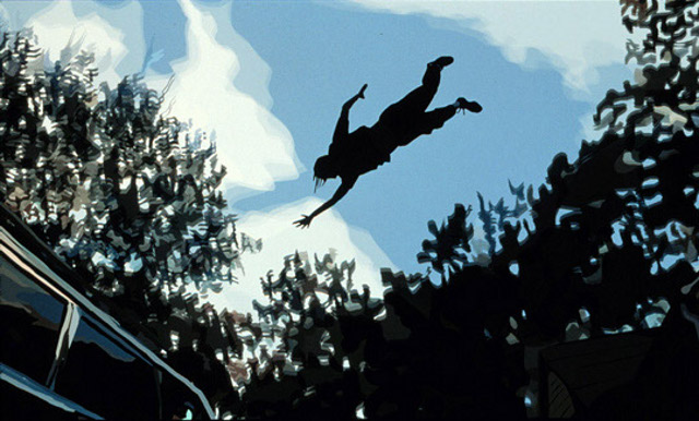
In the past, games and other applications adopted particular visual styles out of technical necessity. As is often the case, these restrictions resulted in a diverse blossoming of creative ideas, producing an enormous set of distinctive visual styles and experiences.

Non-photo-realistic Quake

Crucially, the most successful and memorable examples of these were projects that found ways to work in harmony with the restrictions of the medium, rather than attempting to gloss over them.

Rez HD

Advances in computing power and technique provide modern games and applications with a far wider range of options in how to present themselves visually, and yet the greater proportion of them seem content with a conventional and unimaginative 'near-photorealistic' appearance. 
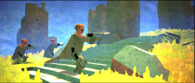
This disappoints me, because I feel that projects that opt for a more highly stylised look, when appropriately chosen, can create a vastly more striking and memorable artistic experiences. This is true in movies and all kinds of art.

Waking Life

As an amateur graphics programmer, I don't have large resources nor much experience to throw at the problem, so my options and my abilities are limited. But, like a good artist, I believe it should still be possible to create things that are both strikingly beautiful and highly functional, either by working with the restrictions of the medium, or by finding creative ways to exploit or extend them.

Love

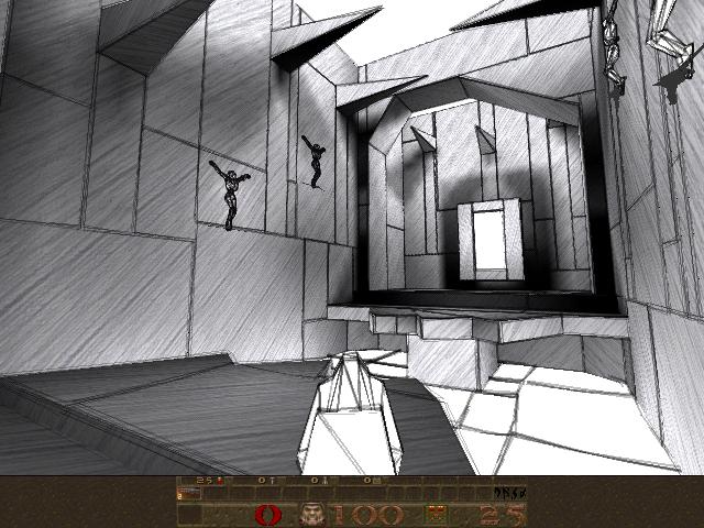
In particular, the kind of minimal, clean-lined aesthetic that amateur OpenGL programs take on by default are useful for their crisp precision, as charting and visualisation tools. But above that, I love them for their stark minimalism, their clean lines and homogeneous fields of colour.

Tron Legacy

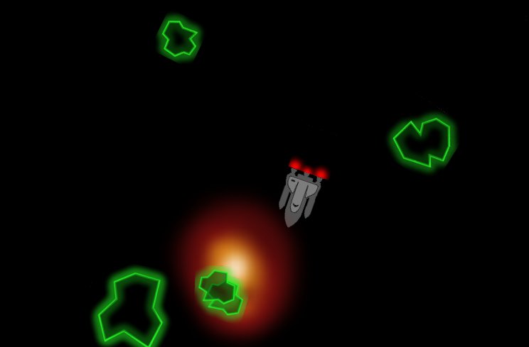
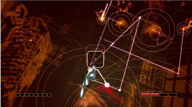
I wish more professional game developers had an incentive to aim for less conventional aesthetics - whether they be deliberately retro, or else striking out in some new direction of their own. It's that brave minority of projects which do this which form my inspiration.

Starting Point

I'm assuming we already have a minimal OpenGL application, that:

  • Opens a window
  • Provides an OpenGL context for us to render to
  • Sets appropriate 3D projection matrix
  • Sets the initial modelview matrix state based on the position and orientation of a 'camera' object
  • Calls our empty 'draw' function once per monitor refresh.

This results in a blank screen, at 60fps. Here's a screenshot, so you can see exactly what it's doing:

A blank screen

I'm using pyglet & PyOpenGL for this, but this isn't important. Any framework that provides the above abilities, such as PyGame, along with bindings to OpenGL, will be just fine. Whichever framework you use, this minimal application might take on the order of about 150 lines of code, and is covered in countless tutorials all over the web.

From here on in I plan to show (or at least describe) pretty much all of the code that I add on top of this minimal OpenGL loop.

Goal

To begin with, I'm going to lead you as quickly as I can through a Shape class, that model 3D shapes, in a way useful for the creation of geometry, and then a Glyph class that converts these geometries into arrays for OpenGL. Finally these arrays get passed into a Render class, which simply calls glDrawElements to render them.

Our Goal

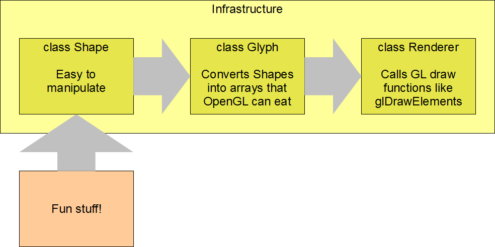
Once the above infrastructure is in place, we can have some fun generating interesting shapes to make pretty pictures with. The conventional way to provide geometry to your OpenGL code is by loading your data from files. Today though, I want to stick with generating geometry from code, to see where that leads.

Modelling Polyhedra

A polyhedron is a 3D shape with flat faces and straight edges. We can model coloured polyhedra using a simple Shape class:

Vec3 = namedtuple('Vec3', 'x y z')
Color = namedtuple('Color', 'r g b a')

class Shape(object):

    def __init__(self, vertices, faces, face_colors):
        # list of Vec3s
        self.vertices = vertices

        # list of faces, each face is a list of indices into 'vertices'
        self.faces = faces

        # List of colors, one per face
        self.face_colors = face_colors

An instance of this class, for example, might represent a yellow cube, or a tetrahedron with green and black faces, or any other coloured polyhedron we can imagine.

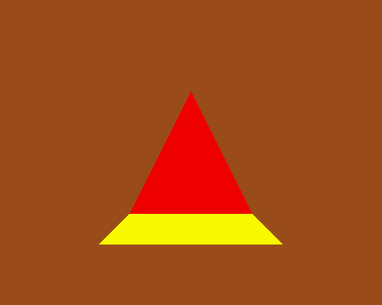
To demonstrate how classes Shape, Glyph and Render hang together, let's examine an even simpler example, a yellow triangle joined to a red square:

Red Triangle & Yellow Square

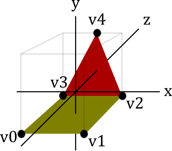
You can see this geometry features five vertices (v0 to v4), which are used by the two faces. This might be represented by an instance of Shape:

v0 = Vec3( 1,  1, 0)
v1 = Vec3( 1, -1, 0)
v2 = Vec3(-1, -1, 0)
v3 = Vec3(-1,  1, 0)
v4 = Vec3( 1,  0, 2)

red = Color(255, 0, 0, 255)
yellow = Color(255, 255, 0, 255)

shape = Shape(
    vertices=[v0, v1, v2, v3, v4],
    faces=[
        [2, 3, 4],    # f0, triangle
        [0, 1, 2, 3], # f1, square
    ],
    face_colors=[red, yellow],
)

The integers in the 'faces' member are indices into the vertices list. So the triangular face, for example, is formed by linking vertices 2, 3 and 4.

Step 1. Creating a Ctypes Vertex array

In order to render our Shape, we need to convert it to some ctypes arrays that OpenGL will eat:

  • glvertices - an array of GLfloats (three for each vertex)
  • glindices - an array of GLubytes (one for each index of each face)
  • glcolors - an array of GLubytes (four for each vertex)

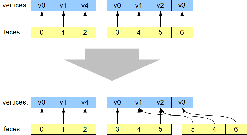
To generate glvertices, we need to dereference the indices in Shape.faces, to produce a new list of vertices, rearranged into the order they are going to be drawn:

Step 1. Dereference indices

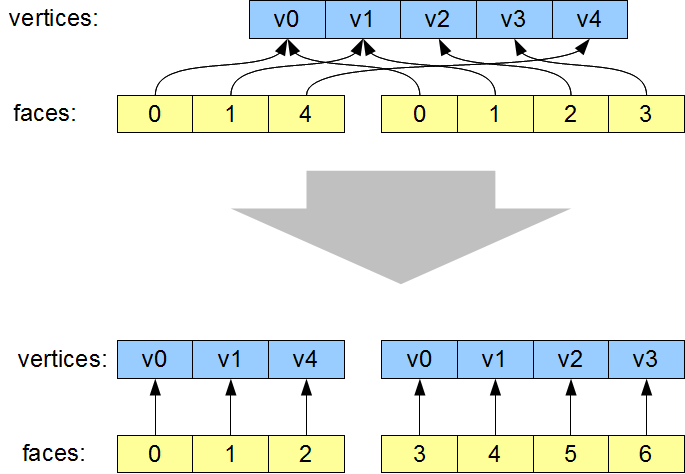
The most visible aspect of this change is that the vertices are re-ordered, such that the indices now simply read '0, 1, 2, 3, 4, 5...'. However that isn't actually necessary. The important part of this transformation is that vertices which are re-used are now duplicated in the vertex list. For example v0 now occurs twice. As a result of this vertex duplication, one the two instances of '0' in the faces lists now instead reads '3' (referencing the new second copy of v0).

This duplication of vertices is required, because when v0 is used for the first time, it is as part of the red triangle, and when it is used the second time it is as part of the yellow square. The color of the vertex changes from one occurrence to the next. All the attributes of a vertex (position, color, texture co-ords, normals, etc) are treated as an atomic unit, so whenever any attribute changes, as the color is changing here, the vertex position needs to be redundantly specified again, so as to create a new unique vertex with its own unique attribute values. Even if the color of v0 in our example was identical for each use, we will see later that other vertex attributes such as surface normals will still differ. Don't sweat trying to eliminate these redundancies, they are necessary, unless every single attribute of the re-used vertex (including surface normals) are identical.

The code in Glyph.get_glverts() performs this dereferencing step:

class Glyph(object):

    def get_glverts(self, shape, num_glverts):
        glverts = chain.from_iterable(
            shape.vertices[index]
            for face in shape.faces
            for index in face
        )
        ArrayType = GLfloat * (num_glverts * 3)
        return ArrayType(*glverts)

This uses a generator to produce the vertices in the order that we need them. 'ArrayType' shows the standard idiom to create a ctypes array - we take the datatype of the array elements, in this case GLfloat since our vertex positions consist of three floats, and multiply it by the required length of the array. This yields a new array type. The final return statement instantiates this array type using the data supplied by the glverts generator.

Step 2. Creating Ctypes Index Arrays

The second job Glyph has to do is create a ctypes indices array, which is derived from the Shape's faces. In doing this, it has to break the Shape's faces down into individual triangles.

Step 2. Tessellate indices

The vertex list is unchanged by this step, and the first face - the triangle - is also unchanged. The second face, the square, has been broken into two triangles.

There are well-known algorithms for breaking an arbitrary polygon down into individual triangles. Using the utility functions found in the GLU library, this can be done in about 150 lines of Python. But in the interests of keeping it simple, I decided to restrict our code to just handling convex faces. Tessellating these faces can be done using a 
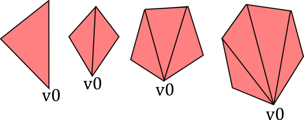
considerably simpler algorithm:

def tessellate(face):
    '''
    Break the given face into triangles.
    e.g. [0, 1, 2, 3, 4] ->
    [[0, 1, 2], [0, 2, 3], [0, 3, 4]]
    Does not work on concave faces.
    '''
    return (
        [face[0], face[i], face[i + 1]]
        for i in xrange(1, len(face) - 1)
    )

We again use a generator, to simply join up the face's first vertex with all the other vertices, like this:

Tessellation of convex faces

Now we have our tessellate function, Glyph can now create the glindices array in much the same way as it generated the glvertices. I wasn't smart enough to write this as a generator first time around, I presume it would require more than one generator to do it (anyone?), so I'm needlessly creating an in-memory copy of the sequence, but it turns out I need to take its length right afterwards anyway, so what the heck:

class Glyph(object):

    def get_glindices(self, faces):
        glindices = []
        face_offset = 0
        for face in faces:
            indices = xrange(face_offset, face_offset + len(face))
            glindices.extend(chain(*tessellate(indices)))
            face_offset += len(face)
        ArrayType = GLubyte * len(glindices)
        return ArrayType(glindices)

This is more complex than get_glvertices because it is performing both of the transformations described in steps 1 and 2. But it's still pretty straightforward. Note that the type of the index array will have change from GLubytes to GLushorts (or GLuints) if the number of vertices rises above 256 (or 65,536.)

Step 3. Creating Ctypes Color Arrays

Finally, we need an array of vertex colors. This is the simplest of the lot, generated by repeating the face_color for each face, once per vertex:

class Glyph(object):

    def get_glcolors(self, faces, face_colors, num_glvertices):
        glcolors = chain.from_iterable(
            repeat(color, len(face))
            for face, color in izip(faces, face_colors)
        )
        ArrayType = GLubyte * (num_glvertices * 4)
        return ArrayType(chain(*glcolors))

First Light

It's might seem like a teensy bit of a slog to get here, but it hasn't been more than sixty lines of code, and now we're in a position to pass our ctypes arrays into OpenGL's drawElements. This happens in our Render.draw() method:

class Render(object):

    def draw(self, world):
        for item in world:
            glVertexPointer(3, GL_FLOAT, 0, item.glyph.glvertices)
            glColorPointer(4, GL_UNSIGNED_BYTE, 0, item.glyph.glcolors)

            # TODO: handle the item's position and orientation

            glDrawElements(
                GL_TRIANGLES,
                len(item.glyph.glindices),
                GL_UNSIGNED_BYTE,
                item.glyph.glindices
            )

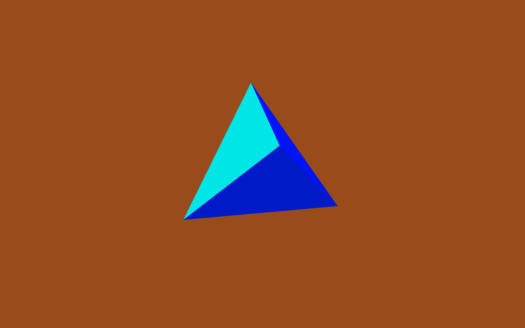
This is canonical OpenGL render code, so I'm not going to dissect it, but now we get some actual visible output:

Red triangle, yellow square

Hooray! \o/ We can move our camera position around, and view this 3D object from different angles.

There's a minor wrinkle here that I'm glossing over. I've turned on backface culling, so the triangle and square aren't visible if we view them from the back. For all our future examples I plan on using closed polyhedra, so we won't be able to see the 'backs' of the faces - those will be on the inside of the polyhedron.

The Fun Stuff

So now we've got all our infrastructure in place, we can start creating 
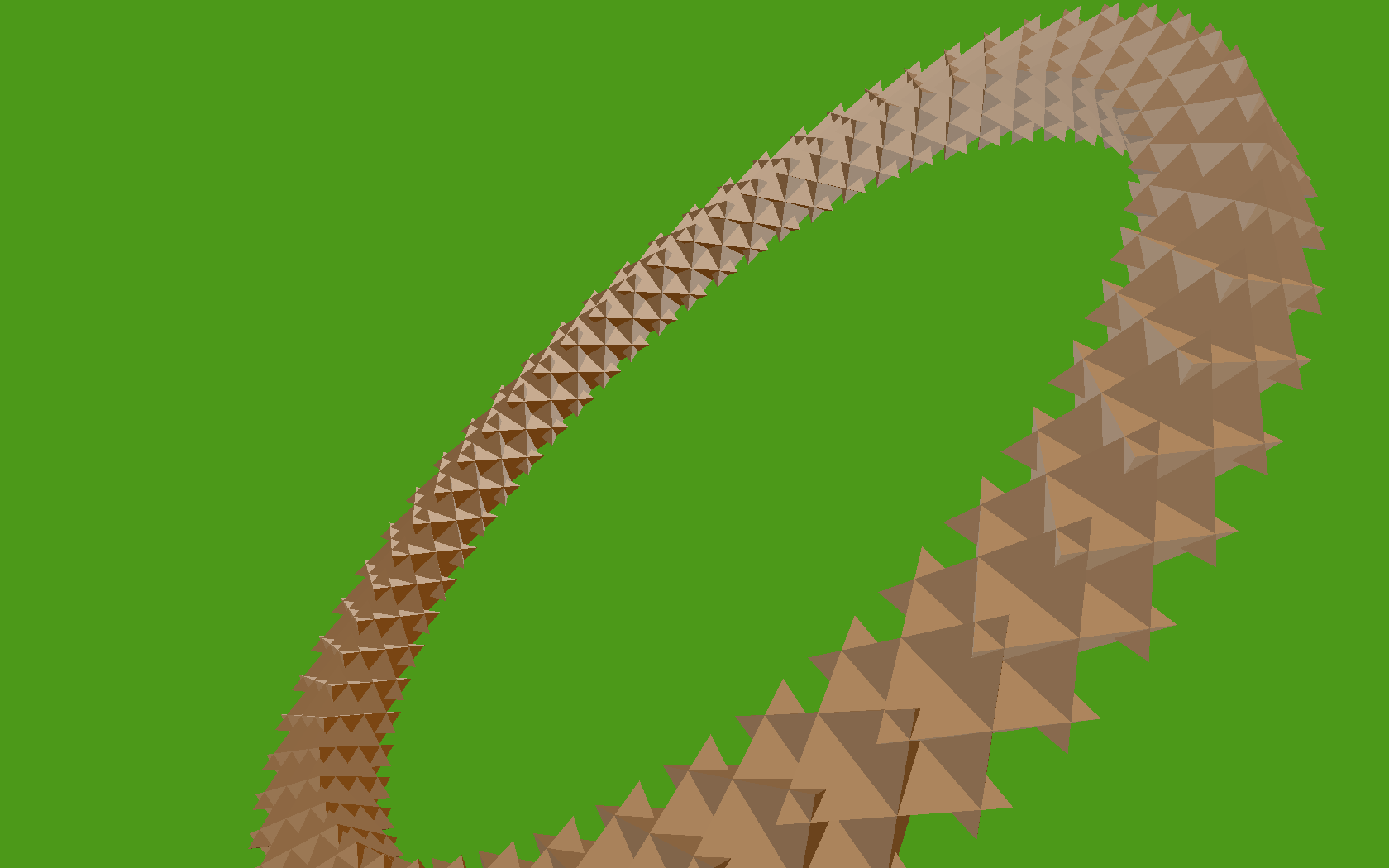
factory functions to churn out some Shapes. Let's start with something 
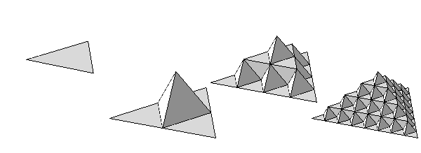
straightforward, a tetrahedron (triangle-based pyramid):

def Tetrahedron(edge, face_colors=None):
    size = edge / sqrt(2)/2
    vertices = [
        (+size, +size, +size),
        (-size, -size, +size),
        (-size, +size, -size),
        (+size, -size, -size),
    ]
    faces = [ [0, 2, 1], [1, 3, 0], [2, 3, 1], [0, 3, 2] ]
    return Shape(vertices, faces, face_colors)

Which produces a tetrahedron:

A tetrahedron

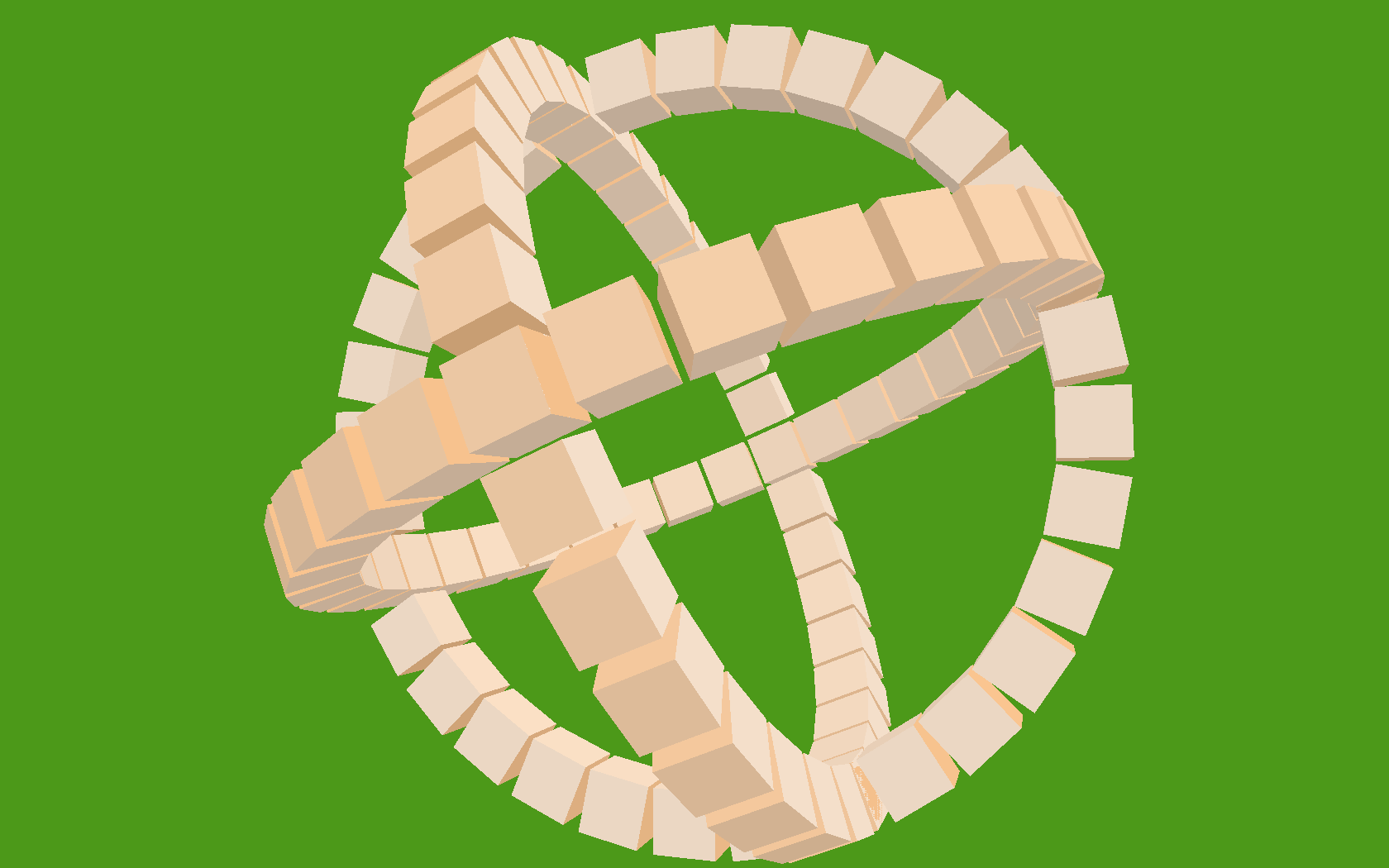
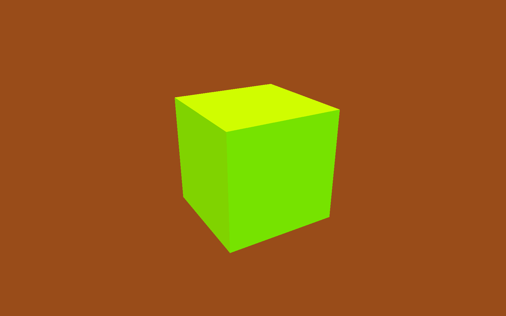
Then a cube factory:

def Cube(edge, face_colors=None):
    e2 = edge / 2
    verts = list(itertools.product(*repeat([-e2, +e2], 3)))
    faces = [
        [0, 1, 3, 2], # left
        [4, 6, 7, 5], # right
        [7, 3, 1, 5], # front
        [0, 2, 6, 4], # back
        [3, 7, 6, 2], # top
        [1, 0, 4, 5], # bottom
    ]
    return Shape(verts, faces, face_colors)

The six faces are quite evident, but the use of itertools.product to produce the list of vertices perhaps deserves a bit of exposition. It's an inspired tip from ΤΖΩΤΖΙΟΥ. Just to spell it out in longhand:

>>> from itertools import repeat, product
>>> list(product(*repeat([-1, +1], 3)))
[(-1, -1, -1), (-1, -1, 1), (-1, 1, -1), (-1, 1, 1),
 (1, -1, -1), (1, -1, 1), (1, 1, -1), (1, 1, 1)]

So there are the eight vertices of the cube, and that gets us the following:

A cube

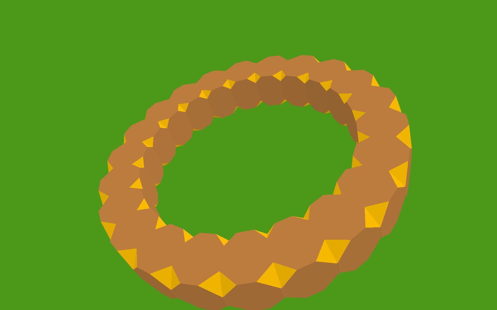
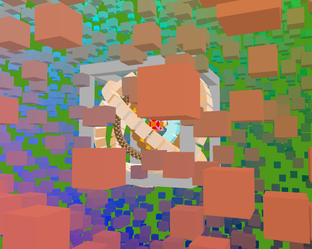
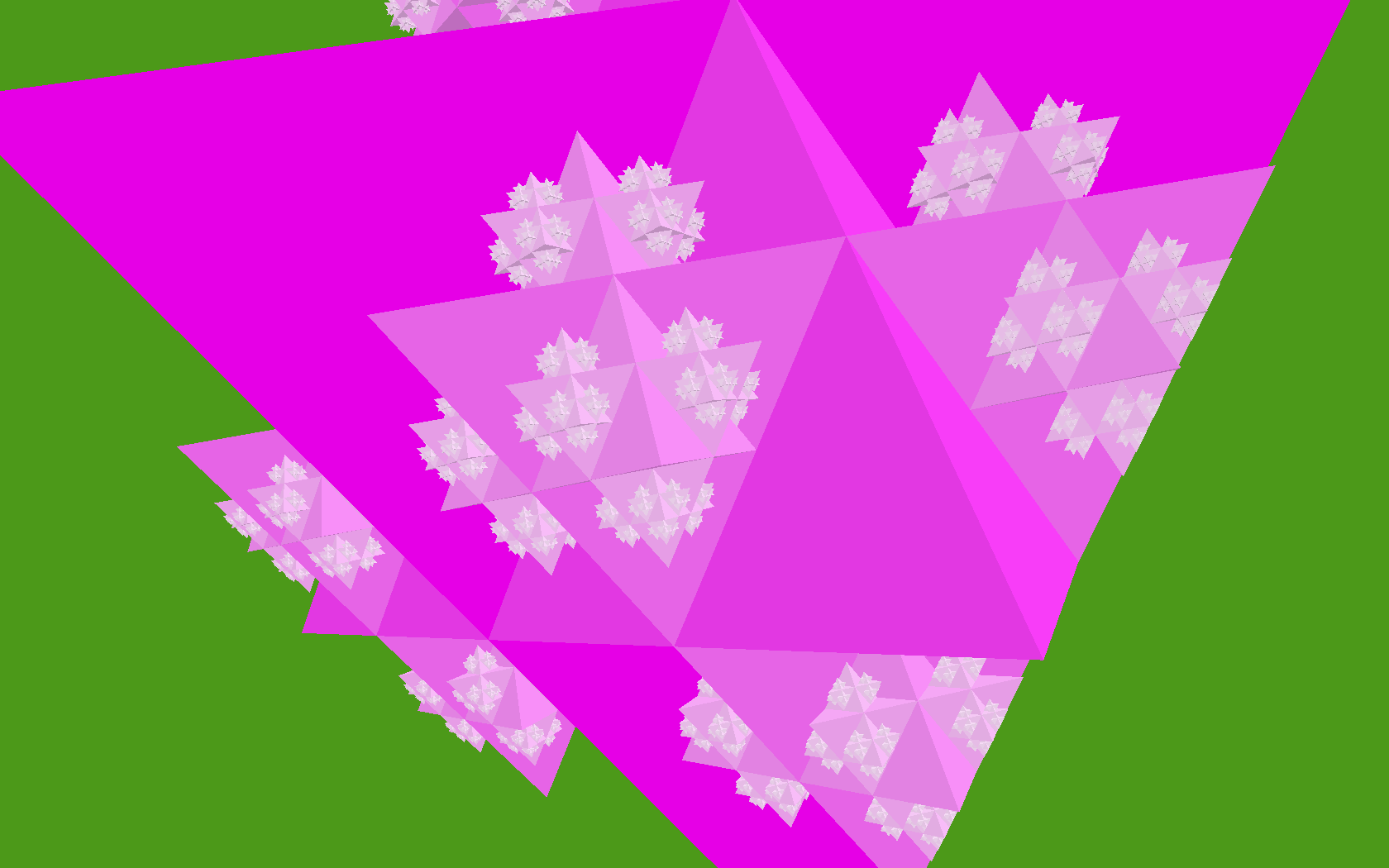
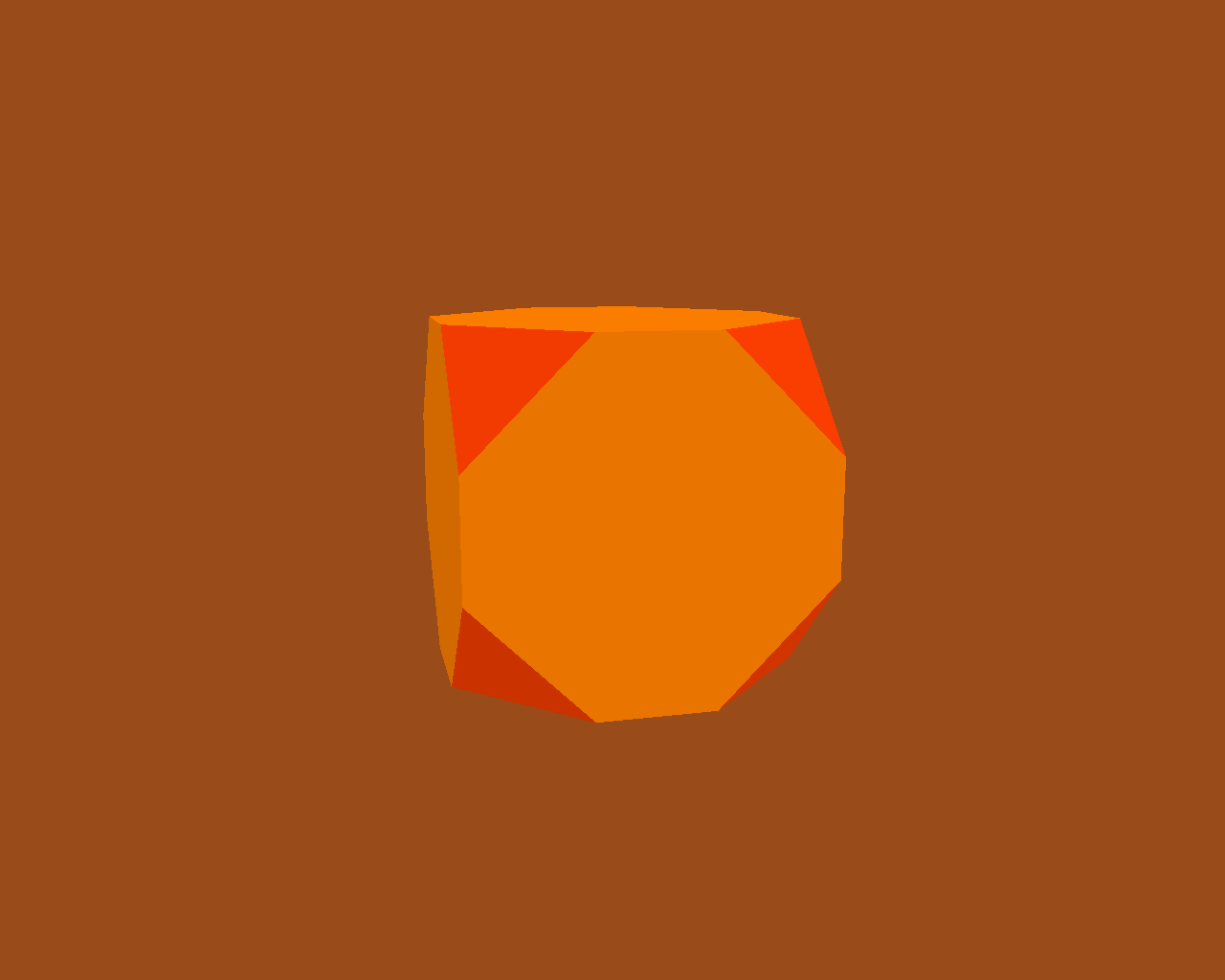
We can add a few more vertices and faces, to make ourselves a truncated cube:

A truncated cube

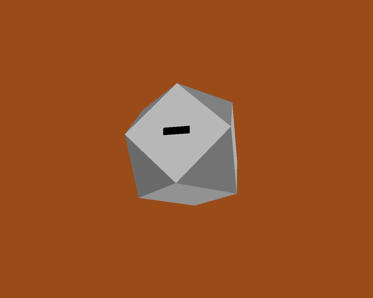
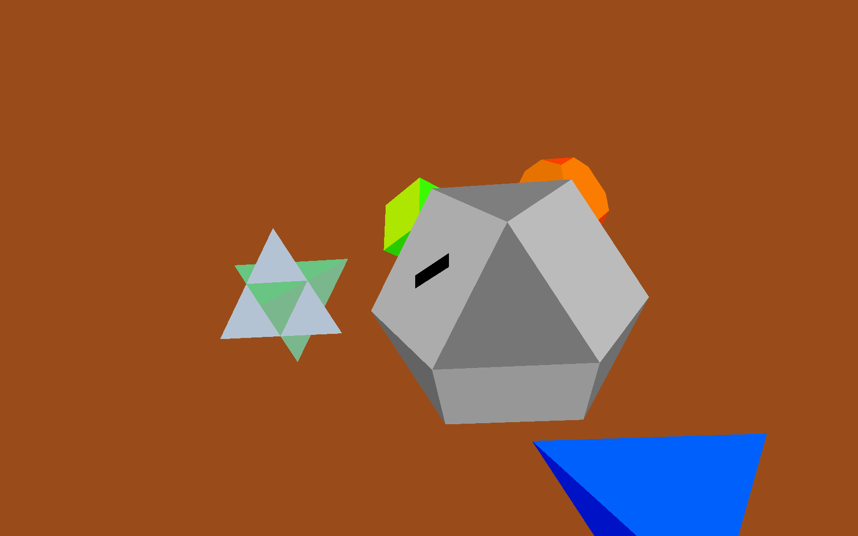
Once we've got truncated cubes, we might as well add one last face to form the entrance:

A truncated cube with entrance

There's nothing to stop us adding several of these shapes into the world at once, but since we haven't yet moved any of them away from the origin, they just sit there, embedded within one another:

A cube and tetrahedron interpenetrate

A truncated cube with two tetrahedrons

Moving objects around

In our earlier Render.draw() method, we left a 'TODO' comment in place, to note that we weren't yet handling item positions and orientations. Here's what Render.draw looks like when we fill that code in:

class Render(object):

    def draw(self, world):
        for item in world:
            glVertexPointer(3, GL_FLOAT, 0, item.glyph.glvertices)
            glColorPointer(4, GL_UNSIGNED_BYTE, 0, item.glyph.glcolors)

            glPushMatrix()
            glTranslatef(*item.position)
            glMultMatrixf(item.orientation.matrix)

            glDrawElements(
                GL_TRIANGLES,
                len(item.glyph.glindices),
                GL_UNSIGNED_BYTE,
                item.glyph.glindices
            )
            glPopMatrix()

Again, this is very standard OpenGL usage. To set an item's position attribute, I'm going to use a bit of code that I already snuck into the demo without telling you about. It's the code that moves the camera around in space. A simplified version is here, class Orbit, which will return a new position each time it gets called. The locus of this position is an orbit around the origin:

class Orbit(object):
    def __init__(self, distance, speed, phase=None):
        self.distance = distance
        self.speed = speed
        if phase is None:
            phase = random.uniform(0, 2 * pi)
        self.phase = phase

    def __call__(self, time):
        bearing = time * self.speed + self.phase
        x = self.distance * math.sin(bearing)
        z = self.distance * math.cos(bearing)
        return Vec3(x, 0, z)

The actual camera uses a slightly longer version I call WobblyOrbit (not shown), which operates in exactly the same way. Any 'mover' class, i.e. one that returns a Vec3 position when called, can be used to move the camera, or any other item, around in space:

class GameItem(object):
    def __init__(self, ** kwargs):
       self.__dict__.update(** kwargs)

world.add( GameItem(
    shape=Cube(1, repeat(red)),
    mover=Orbit(distance=20, speed=4),
) )

# then, in world.update():
for item in self.items:
    if item.mover:
        item.position = item.mover(self.time)

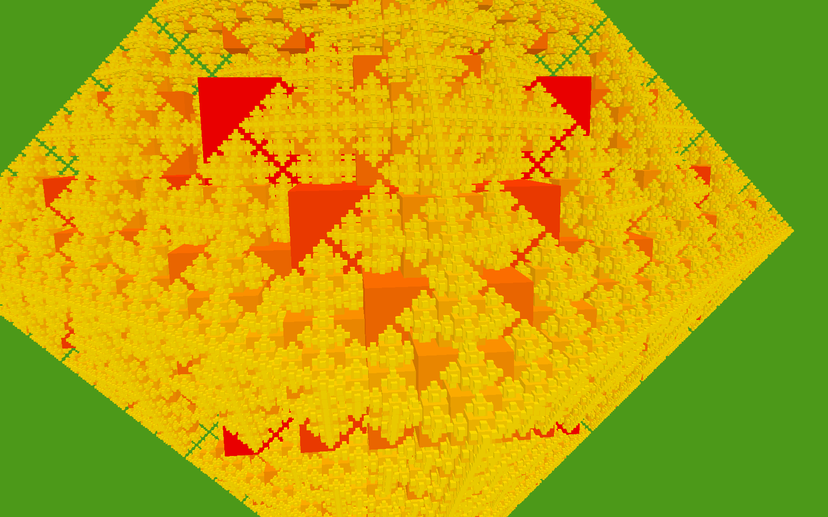
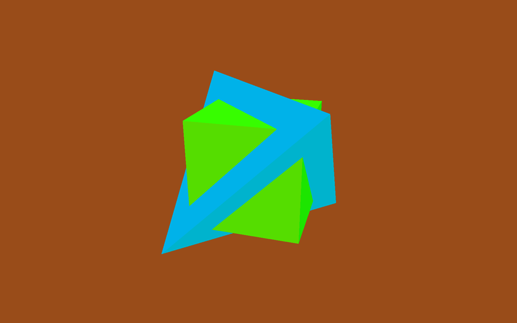
Similarly, we can spin items using 'spinner' classes, that tweak an item's orientation as time goes by.

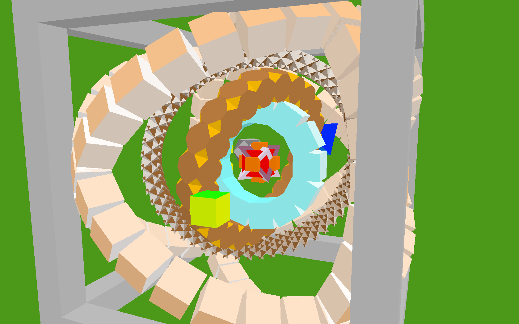
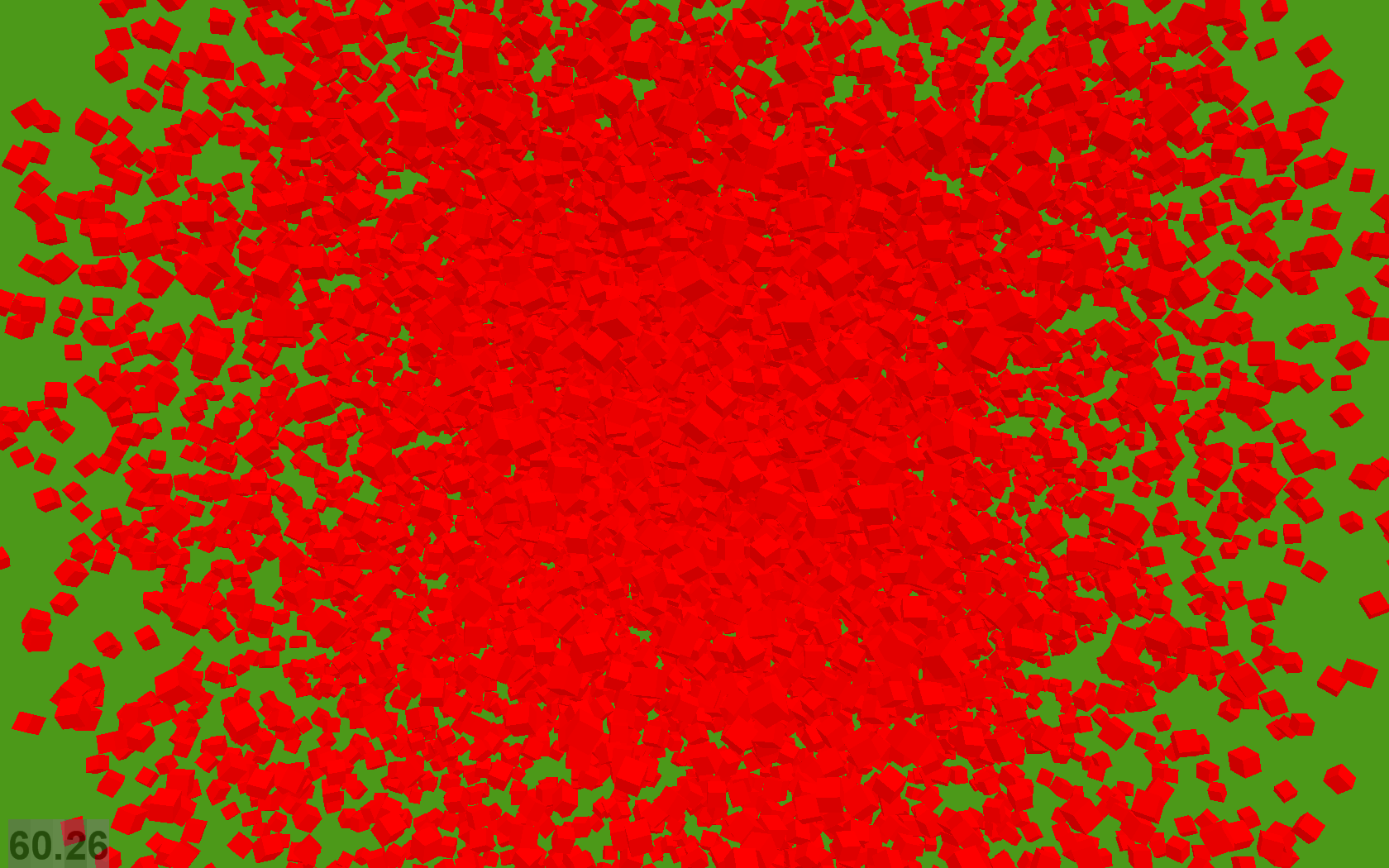
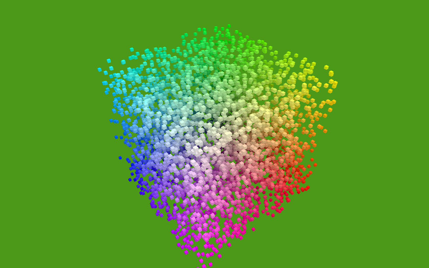
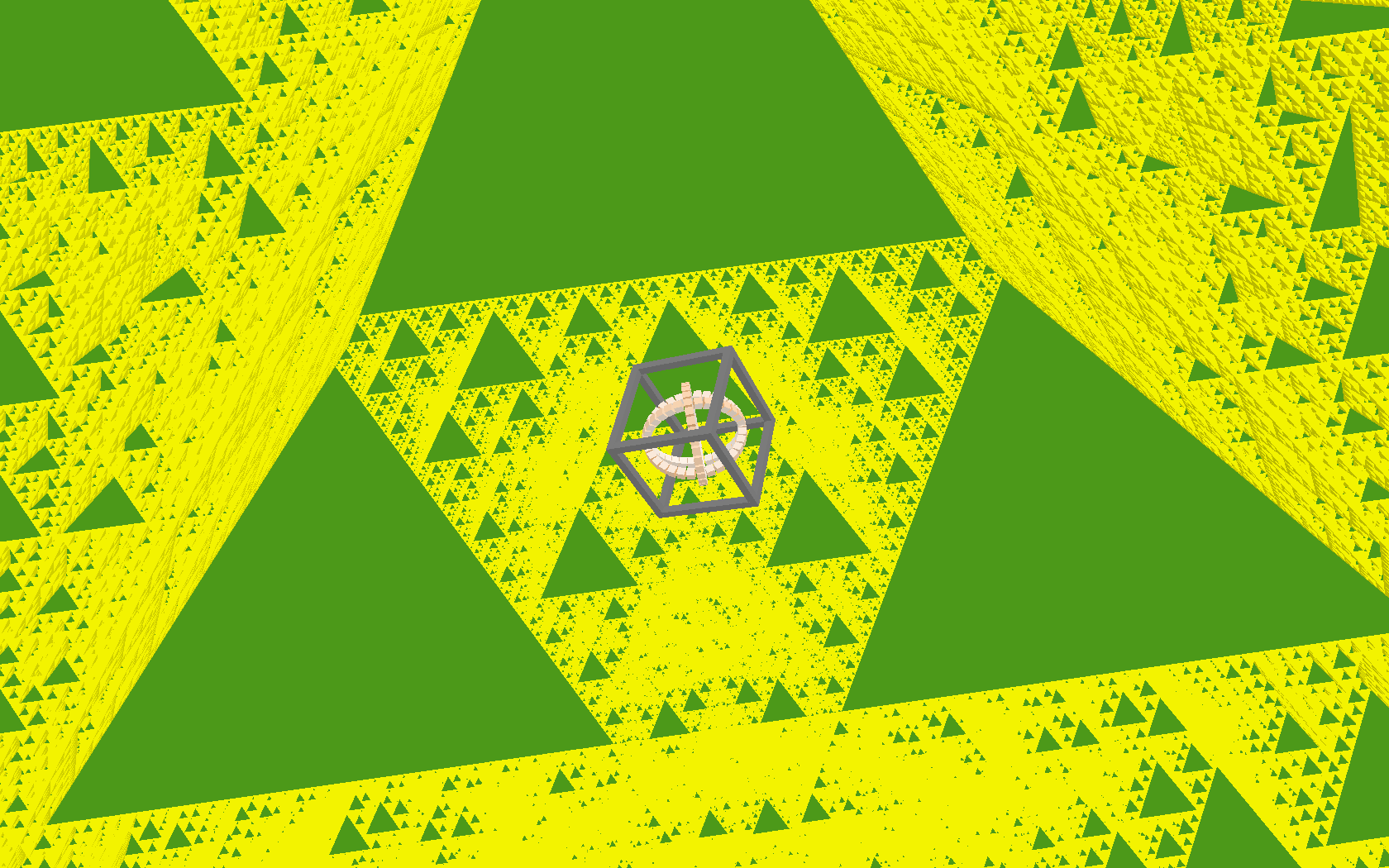
With these all in place, we can now add many Shapes to the world, each moving and rotating independently:

Several independantly positioned and oriented shapes

Next week: Composite Shapes...

This is all great as far as it goes, but it turns out we have a performance problem. Adding more than about 450 shapes at once starts to slow down below 60fps (This is all on my trusty 2005-era Thinkpad T60 laptop.) The bottleneck turns out to be in our Render.draw() loop. Each of those OpenGL functions are from (wrappers around) the OpenGL C library, and calling across the Python / C boundary like this incurs a per-function call overhead. Also, a second looming problem is that creating more interesting shapes is going to become more onerous and error-prone, as we create longer and more complex lists of vertices and faces in our code.

One partial solution to both these problems is to use composite shapes, in which we can compose many copies of our basic shapes into one single, more complex shape. This will allow us to use algorithmic means to produce more fun geometry, and will also help us draw more complex shapes, composed of many simpler shapes, without requiring several separate OpenGL function calls for each of the simple shapes.

On to Part 2 >>

Loving EuroPython Tutorials

I've been loving the two days of tutorials preceding the EuroPython conference. This morning I attended Richard Jones' splendid Introduction to Game Programming. It was an absolute pleasure to be walked through the creation of an example game like this, using Python game libraries like pyglet and Cocos, by someone who really knows what he's doing. Also, it's nice to have something visible to show after a morning's work:

My asteroids.

(Michael your idea of making engine thrust always visible was exactly what I needed to help me capture the screenshot.)

The code is based very heavily on samples that Richard provided and talked us through in great detail, so although I now understand it pretty thoroughly, I can't take much credit. Excepting, that is, for a handful of minor tweaks I couldn't resist making along the way, like the flickery animated engine thrust, that made me gurgle with delight.

For the artwork, I stole the shuttle icon (sssshhhhhh!), added the engine thrust, and created the asteroids themselves entirely from scratch in Gimp. They are just rotatable bitmaps, albeit designed in homage of vector graphics of yore, complete with simulated CRT glow. Brilliant!

Undocumented feature of the week: $PIP_DOWNLOAD_CACHE

Use Python? You should be using Pip. A replacement for easy_install, that supports uninstalling and plays nice with virtualenv. An apt-get for Python packages, if you will.

It has a marvellous undocumented feature. Set the environment variable PIP_DOWNLOAD_CACHE to prevent re-downloading the same packages repeatedly when setting up environments on the same machine:

> set | grep PIP
PIP_DOWNLOAD_CACHE=C:\Documents and Settings\jhartley\.pip_download_cache

> pip install mock
Downloading/unpacking mock
Creating supposed download cache at C:\Documents and Settings\jhartley\.pip_download_cache
 Downloading mock-0.7.0b2.zip (242Kb): 242Kb downloaded
 Storing download in cache at c:\documents and settings\jhartley\.pip_download_cache\http%3a%2f%2fpypi.python.org%2fpackages%2fsource%2fm%2fmock%2fmock-0.7.0b2.zip
[snip]
Successfully installed mock

> pip uninstall mock
[snip]
 Successfully uninstalled mock

> pip install mock
Downloading/unpacking mock
 Using download cache from C:\Documents and Settings\jhartley\.pip_download_cache\http%3A%2F%2Fpypi.python.org%2Fpackages%2Fsource%2Fm%2Fmock%2Fmock-0.7.0b2.zip
[snip]
Successfully installed mock

(This text is copied from my unholy bastardised shell of choice at work, Windows CMD shell with Cygwin binaries foremost on the PATH.)

Using the download cache like this is substantially faster. Exactly what you need if you're continually setting up environments under various version of Python for testing or what-have-you.

The directory is created if it doesn't exist. Network access is still required when installing like this, presumably for the version checks.

Thanks to the irrepressible fuzzyman for bringing this to my attention.

I am such a child

Dear Julio,

Many thanks for considering me for this opportunity. I feel as though my skills are a good match for the position, and would like you to consider my application.

I feel as though this is the start of a new phase in life for me, as though I have really rounded a corner. I have not used a computer, but my nephew says he will meet me tomorrow afternoon to teach me how to do it. Also, my therapist says that my bouts of incoherent rage will continue to diminish, so that will be good in my new job. My probation for stealing from my previous employer is almost up.

I am high, but I can absolutely have this under control and be completely sober by Monday, when I trust you will call me at your earliest convenience.

Best regards,

Jonathan Hartley

-------- Original Message --------


Subject: offer number 078 Date: Fri, 9 Jul 2010 17:28:46 -0500 From: To:


My name is Julio YEPES, I am a hiring manager with ...

More Colored Terminal text on Windows: AnsiCon

A reminder for myself:

ANSI escape characters don't work properly in Windows terminals:

Before: Raw ANSI codes. Not nice.

To make them work properly, use AnsiCon. Unzip it somewhere permanent (eg. %ProgramFiles%\ansicon) and install it with:

ansicon.exe -i

start a new terminal, and lo:

After: Pretty.

Fine tune the appearance of the programs generating the color, for example customise 'hg diff' by editing \~/.hgrc:

[extensions]
color =

[color]
status.modified = yellow bold
status.unknown = white
status.deleted = red_background white bold

diff.deleted = red bold
diff.inserted = green bold
diff.file_a = white
diff.file_b = white
diff.diffline = white_background black
diff.extended = yellow bold
diff.hunk = underline black
diff.changed = yellow bold

Fine-tuned

ANSI is correctly stripped out if the output of a program is not a terminal, so the colored output won't interfere with saving to files nor machine-parsing of the text:

Filtered

Finally, insert some ANSI codes into your prompt, by setting environment variable PROMPT:

set PROMPT=$E[0;36m$P$_$E[36;1m$G$E[0m$S

Colored Prompt

Multiple posts on colors and terminal text is perhaps a bit obsessive of me. I think I'm all done now.

More OpenGL from Python

My talk, Flying High : Hobbyist OpenGL from Python, was accepted for EuroPython 2010, \o/. I don't want to reveal the best bits of my talks, but to whet people's appetite, this is some of what my initial preparation involved.

One thing I'm keen on talking about is algorithmic generation of interesting geometry. This is an area in which the flexibility and expressiveness of Python can really shine.

I started with a quick Shape class, to model the vertices and faces of an arbitrary polyhedra (3D shapes with flat faces and straight edges):

Position = namedtuple('Position', 'x y z')

class Shape(object):
    def __init__(self, vertices, faces, color):
        self.vertices = [Position(*v) for v in vertices]
        self.faces = faces
        self.color = color

Each face of the shape is represented as a list of integer indices into the vertex list. The 'faces' attribute is a list of all faces. The color attributes is just a 4 element tuple: (r, g, b, alpha). This class can now be instantiated by factory functions to form particular 3D shapes, such as red cubes or blue tetrahedrons:

def Cube(edge, color):
    verts = [
        (-edge/2, -edge/2, -edge/2),
        (-edge/2, -edge/2, +edge/2),
        (-edge/2, +edge/2, -edge/2),
        (-edge/2, +edge/2, +edge/2),
        (+edge/2, -edge/2, -edge/2),
        (+edge/2, -edge/2, +edge/2),
        (+edge/2, +edge/2, -edge/2),
        (+edge/2, +edge/2, +edge/2),
    ]
    faces = [
        [0, 1, 3, 2], # left
        [4, 6, 7, 5], # right
        [7, 3, 1, 5], # front
        [0, 2, 6, 4], # back
        [3, 7, 6, 2], # top
        [1, 0, 4, 5], # bottom
    ]
    return Shape(verts, faces, color)

A class called 'Glyph' will convert a Shape instance into the set of ctypes arrays that need to be passed to OpenGL:

The real Glyph class also creates arrays for color, and array indexes as well as vertices.

Finally, we have a renderer, whose 'draw' method is invoked by our window draw event. This iterates through all items in our world that have a Glyph attribute, drawing each of them:

def draw(self, items):
    for item in items:
        gl.glPushMatrix()

        gl.glTranslatef(*position)

        # TODO: orientation

        gl.glVertexPointer(3, gl.GL_FLOAT, 0, item.glyph.glVerts)
        gl.glColorPointer(4, gl.GL_FLOAT, 0, item.glyph.glColors)
        gl.glDrawElements(
            gl.GL_TRIANGLES,      # draw disjoint triangles
            len(glyph.glIndices), # number of vertices to draw
            gl.GL_UNSIGNED_SHORT, # type of indices
            glyph.glIndices)      # index array

        gl.glPopMatrix()

So we add a couple of interpenetrated Cube() shaped items into our world:

white = (1, 1, 1, 1)
red = (1, 0, 0, 1)

world.add( GameItem(
    position=Position(0, 0, 0),
    shape=Cube(2, white),
    glyph=Glyph(),
))
world.add( GameItem(
    position=Position(1, 1, 0),
    shape=Cube(1, red),
    glyph=Glyph(),
))

and running the program renders them:

The flat shading is because we have no lighting yet. That gets fixed soon.

Each cube is being drawn by a separate call to glDrawElements. This is fine for small numbers of items, but for performance we'll want to compose our geometry into single arrays that can be rendered by a single call to glDrawElements. To do this, we create a CompositeShape object, that contains several Shapes, and exposes 'vertices' and 'faces' attributes just like a regular Shape, which aggregate the geometry of all their subordinate Shapes.

class CompositeShape(object):

    def __init__(self):
        self.children = []

    def add(self, child, offset=None):
        if offset is None:
            offset = Position(0, 0, 0)
        self.children.append((child, offset))

    @property
    def vertices(self):
        return (vert + offset
                for shape, offset in self.children
                for vert in shape.vertices)

(The real CompositeShape class also defines 'faces', which is elided here.) Instances of CompositeShape can be passed directly to our unmodified Glyph class, allowing us to construct complex geometries out of many individual parts, but now they are all rendered in a single OpenGL API call.

A new factory function creates a fancy CompositeShape called a CubeCluster, consisting of many randomly-positioned small cubes, each one colored by its position in (r, g, b) space. These are surrounded by a sprinkling of black cubes, a large translucent cube-shaped skin:

and buried deep at the centre of the CubeCluster is some sort of mysterious structure:

So using this code, I get 60fps on modest hardware (my 2005 end-of-line Thinkpad T60, an ATI Radeon X1400) while rendering either:

  • 800 independently moving and rotating items, each a simple cube (8 vertices, 8 colors, no normals, 36 indices = 12 triangles) for a total of 9600 triangles.

or

  • 1 composite item comprising 9,000 cubes, (108,000 triangles)

or any linear interpolation between these two extremes. (Update: see improvement on this noted in the final paragraph.)

I've done nothing to try and tune the performance, in particular I'm updating and rendering every single item every frame, and I'm not using vertex buffers, so I suspect my geometry is being sent over the bus to the GPU every frame. So presumably this can be still be much improved.

Next I add some basic lighting, so that our cubes don't look so flat shaded. Lighting needs to know normals, the vector at right angles to a face, so that it can figure out how how strongly each face is illuminated. So our Glyph needs to start generating an array of normals for each vertex.

def get_normal(face, vertices):
    v0 = vertices[face[0]]
    v1 = vertices[face[1]]
    v2 = vertices[face[2]]
    a = v0 - v1
    b = v2 - v1
    return b.cross(a)

class Glyph(object):

    def get_glnormals(self, shape):
        face_normals = (get_normal(face, shape.vertices)
                        for face in shape.faces)
        normals = (normal
                   for face, normal in zip(shape.faces, face_normals)
                   for index in face)

        return gl_array(gl.GLfloat, normals, self.num_glvertices * 3)

This generation of normals also affects the generation of vertex positions, colors and indices, since vertices can no longer be shared between different faces of a cube, because a single vertex position now requires a different normal for each face.

Generating normals made me think more about when I should or should not be using indexed vertex arrays, as opposed to simple contiguous arrays of vertices. My current thoughts on the matter are summarised on this stackoverflow question. If you know a bunch about OpenGL, I'd appreciate you heading over there and setting me straight.

Adding normals increased the vertex count required to draw the same geometry quite considerably, from 8 vertices for a single cube, up to 24. The colors array increases in size correspondingly. Surprisingly, this didn't decrease framerate too much (we went from drawing 9,000 cubes at 60fps down to 8,000.) However, then I converted colors from being floats (eg. white=(1.0, 1.0, 1.0, 1.0), four components for rgb and alpha)) to using unsigned bytes (e.g. white=(255, 255, 255, 255).) This boosted performance noticeably, so now we're up to drawing 12,000 cubes at 60fps, with normals and lighting.

Next up is to start generating some more interesting geometry, other than just a bunch of cubes...

Update: The code that generated the above screenshots is in a Mercurial repo at:\ http://code.google.com/p/flyinghigh-opengl-from-python/

Only the "code" directory is of any interest (the rest is just a dumping ground for my thoughts related to the text of the talk.) There is a hastily-created README in the code directory.

In particular, note that the code may spend a while generating geometry on startup, before displaying anything. This startup time has been fluctuating wildly, as I add new ideas, then refine them to be reasonably performant. To improve performance or startup time, you might want to take a look in the 'flyinghigh/populate_world.py' module and comment out the creation of some of the GameItem instances that are passed to world.add().

Feedback, ideas and questions all welcome.

The Great Resolver IDE Anecdote

Found myself telling this story yet again, so I figured I should just post it here and start linking to it, rather than remembering, retyping and re-embellishing it every time.

Ever since we started at Resolver, developers have been free to choose their own IDE (Integrated Development Environment, although some of the ones I'm going to talk about aren't so integrated, so I guess you should just read 'IDE' herein to mean 'development environment').

Like herding cats, this of course resulted in everyone choosing a different IDE. At one peak, we had fourteen people, and about ten different IDEs. Sigh. To our incredulity though, this worked fine, and everyone was happy. So far, so good.

We pair program, so we see a lot of each other's IDEs. In fact, we end up learning them all pretty thoroughly. Spending eight hours a day, every day, using someone else's IDE, with a bona-fide expert in that IDE sitting in your lap, guiding you through it, will tend to do that. After a few months, we all knew every IDE out there back-to-front. An example of how pairing spreads knowledge.

Every so often, someone would change their mind about their chosen IDE. Having been educated about the alternatives, they would decide to switch. This was also fine, and everyone continued to be happy.

Then, after a few months of this, an interesting thing happened. Gradually, one by one, twelve of our fourteen people each decided, of their own accord, to switch to using either Vi or Emacs.

I regard this of an example of pairing not just spreading knowledge, but spreading enlightenment.

They each had realised that although these hallowed text editors didn't have some of the more advanced features they'd come to expect from an IDE, such as auto-completion or 'go to definition', they were flexible and powerful enough that one could add such features yourself. To do so is a rite of passage for an experienced programmer, akin to Luke building his own lightsaber - so that it's customized to his precise needs, and he understands each nuance of its behaviour.

More than that, all the conveniences of a traditional IDE made it very convenient to do only what the authors of the IDE had envisaged. To do anything else was made very difficult. If you wished to use a different compiler, or write in a different language than those prescribed by your IDE vendor, you were out of luck, and would have to learn an entirely different IDE to do that.

"We shape our tools and afterwards our tools shape us."

  • Marshall McLuhan ('The media is the message' guy)

On one project, or two, this might seem a trivial restriction. Extended over the course of a lifetime, the conveniences shields a developer from learning anything other than how to drive an IDE, and the restrictions become blinkers, crippling their scope and abilities. The IDE is a cage... for your mind.

The outliers are worth noting: We still use Visual Studio on rare occasions, for the lovely built-in GUI designer. The irrepressible Michael Foord loves Wing, and stuck with that. Will Reade, our tame brainiac, stuck with transparent simplicity of the lightweight but surprisingly useful TextPad. Go figure.

Update: The coda to the outliers is also interesting. Nowadays we're embedded in a huge mission to free our codebase from embedded win32 controls, so that we might have a chance of running under Mono, and hence on other platforms. It would be nice if we could escape Windows Forms altogether - I understand WPF would let us display our GUI on the web. Writing this post makes me wonder - if we hadn't been using Visual Studio's convenient GUI designer all along, is it remotely possible that we might have considered our choice of GUI layer more thoroughly? If we hadn't been entranced by the "obviously right" convenience of the Visual Studio GUI designer, might our minds have been free enough to have made this decision right the first time around?